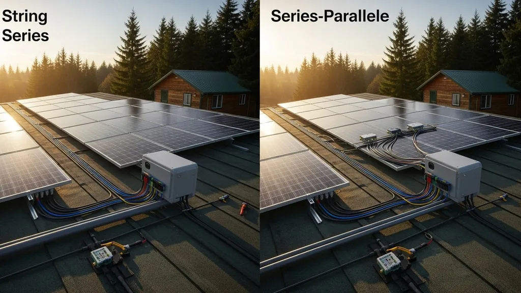
Clear, practical guide to series, parallel, and series-parallel solar panel wiring — pros, cons, diagrams, and which to use for off-grid DIY builds.
Solar Panel Wiring Diagrams: Series vs Parallel
Choosing the right solar panel wiring topology affects system voltage, current, safety, and real-world performance. This guide compares series, parallel, and series-parallel wiring so budget-conscious DIY builders can pick a layout that matches panel count, shading conditions, and the inverter/charge-controller used. It covers simple diagrams, numerical examples, protective components, and when to call a licensed electrician.
TL;DR:
- Series wiring raises array voltage (panels add Vmp/Voc), which suits MPPT controllers and long cable runs; expect higher shading sensitivity and need to check max Voc vs inverter specs.
- Parallel wiring keeps panel voltage the same while currents add, improving shade resilience but requiring thicker conductors, branch fuses, and more combiner hardware.
- Series-parallel mixes strings to scale both voltage and current — match identical panels, use combiner boxes and branch fusing, and verify controller/inverter input ranges before wiring.
Solar Panel Wiring Diagrams: Series vs Parallel — Overview & TL;DR (comparison Table)
Quick Summary of Differences
Imagine a tiny off-grid cabin with three panels on a roof. Wiring them in series increases voltage to feed an MPPT charge controller efficiently, but if one panel is shaded the whole string drops. Wiring them in parallel keeps each panel operating independently but needs heavier gauge cable and a combiner for the higher current. Series-parallel lets the builder scale an array while keeping per-string voltages inside controller limits.
| Configuration | Typical Voc/Vmp behavior | Current | Shading sensitivity | Charge controller/inverter implications | Wiring cost/complexity | Best for |
|---|---|---|---|---|---|---|
| Series | Voltages add (Vmp and Voc sum across panels) | Same as single panel | High — one shaded panel affects whole string unless bypass diodes/optimizers used | Works well with MPPT, must respect max Voc and inverter input range; watch cold-temp Voc | Lower conductor ampacity, simpler routing, need string fuse/MCB | Long runs, small panel count, MPPT controllers |
| Parallel | Voltage stays like one panel; current adds | Currents add (Isc/Ipm sum) | Low — shaded panel mainly loses its output | Suits PWM and MPPT if controller input handles combined current; requires busbars/combiner | Higher copper cost, branch fuses required, thicker main conductors | Shady sites, mixed orientations, microinverter-free designs |
| Series-parallel | Strings of series panels paralleled — scales voltage and current | Scales by number of parallel strings | Moderate — shading on one panel reduces its string, not whole array | Flexible for mid-size arrays; requires combiner box, branch protection, verify string-to-inverter ratios | Moderate complexity: combiner, branch fuses, matched panels | Scalable homesteads, 3–10 kW off-grid systems |
For a practical installer-focused overview of wiring options and the 2023 NEC considerations, see this solar panel wiring guide for installers.
Solar Panel Wiring Diagrams: Series Wiring
Overview of Series Wiring and Sample Diagram
Series solar wiring ties each panel positive to the next panel's negative, forming a string. Voltages add; current stays at the panel's output rating. In practice: if each panel has Vmp = 18 V and Isc = 8 A, three in series give Vmp ≈ 54 V and Isc ≈ 8 A. This higher voltage is ideal for MPPT charge controllers and string inverters that require higher input voltage to maximize power conversion.
Simple labeled diagram (conceptual): Panel A (+) → Panel B (−) to Panel B (+) → Panel C (−) ending at string positive and negative leads to the controller.
Strengths of Series Wiring
- Higher voltage reduces resistive losses for long roof-to-inverter runs; smaller conductor sizes often suffice.
- MPPT controllers perform better when array voltage stays above battery charging voltage plus headroom.
- Simpler wiring layout for a single string — fewer branch connections and combiner boxes.
Weaknesses and Common Pitfalls
- Shading impacts: one partially shaded panel can reduce the entire string’s output unless panels have integrated bypass diodes or module-level power electronics are used.
- Cold-weather Voc rise: panel Voc increases as temperature drops. Designers must compare worst-case Voc (from the panel datasheet using the coldest local temperature) against the inverter/charge controller maximum input voltage and NEC limits. Consult module datasheets and local code before finalizing string length.
- Over-voltage risk: always confirm maximum string Voc vs inverter or MPPT upper limits. Industry guidance and installer resources emphasize verifying cold Voc calculations (see the EcoFlow wiring guide for practical layout notes on inverter selection and string sizing: Solar panel wiring diagram guide).
- Protection: string fuses or an MCB near combiner entries are required where multiple parallel strings exist. Blocking diodes are rarely needed for correctly sized MPPT systems; blocking diodes can cause voltage drop and heat and are typically found in older designs.
Best For: Ideal Use Cases and Examples
- Small arrays feeding an MPPT charge controller with short to moderate runs to the controller.
- Tiny houses with 3–6 panels mounted together and identical module orientation.
- Cases where long DC runs make higher voltage safer and more economical.
Practical example: three panels rated Vmp 36 V (example nominal panels used in some 24 V systems) in series produce Vmp ≈108 V — that would suit an MPPT or string inverter rated for that range but would be too high for a 12 V battery-direct PWM controller. For battery-connected systems, read the inverter/MPPT manual and cross-check against panel Voc at the lowest expected ambient temperature. See our guide on how to connect panels to a hybrid inverter for matching array voltage to inverter specs: connect panels to a hybrid inverter. Battery chemistry affects charge voltage and wiring choices — review lithium vs lead-acid best practices when pairing arrays with battery banks.
Quick Checklist for Series Wiring
- Match panel electrical specs and orientation.
- Calculate worst-case Voc using datasheet temperature coefficients.
- Confirm MPPT/inverter maximum input voltage.
- Include string-level disconnects and proper cable glands at roof penetrations.
Solar Panel Wiring Diagrams: Parallel Wiring
Overview of Parallel Wiring and Sample Diagram
Parallel solar wiring ties all positives together and all negatives together so the array voltage stays equal to a single module while currents add. If a panel provides Voc 21 V and Imp 8 A at Vmp, three in parallel deliver the same ~21 V but current ≈24 A (3 × 8 A).
Simple labelled diagram (conceptual): Panel A (+), Panel B (+), Panel C (+) all join to the positive bus; Panel A (−), Panel B (−), Panel C (−) all join to the negative bus; that bus feeds the controller.
Strengths of Parallel Wiring
- Better partial-shade behaviour: a shaded panel mainly loses its own output instead of dragging down the whole array.
- Mixed-orientation arrays or systems where panels face different angles can be wired in parallel to let each module operate near its optimum.
- Easier to expand by adding branches with fuse protection.
Weaknesses and Typical Issues
- Higher currents require thicker copper conductors, increasing material cost and conductor management complexity. Voltage drop over distance becomes a limiting factor at higher current.
- Each parallel branch generally requires a fuse sized for its short-circuit current to meet overcurrent protection requirements.
- Combiner boxes and busbars add upfront cost and installation time.
- Parallel arrays tied directly to batteries using PWM controllers are common in very low-cost setups, but MPPT systems still prefer higher voltage inputs for efficiency.
Best For: Ideal Use Cases and Examples
- Sites with shade, mixed panel orientations, or where microinverters/optimizers are not being used.
- Small arrays with short runs where thicker conductors are affordable relative to optimizer cost.
- Systems where keeping module voltage near battery voltage is required (e.g., direct 12 V systems), but note that modern MPPT controllers usually outperform PWM even at modest voltages.
Practical example: three panels in parallel each with Isc 9 A produce ~27 A total. If the run to the charge controller is 20 m, the builder must choose cable with sufficient ampacity to limit voltage drop to an acceptable percent (commonly 2–3%). For panel selection in parallel setups, see the list of budget panel options. Thermal performance affects output and sometimes mimics wiring faults; check these cooling tips for panels.
For vendor-level wiring examples that include branch fusing and combiner details, see a technical wiring guide for installers: Wiring guide solar panels.
Practical Tips for Parallel Wiring
- Fuse each branch on the positive conductor at or just above the panel Isc rating.
- Use a combiner box with a labeled bus and neat strain reliefs.
- Size the main positive/negative runs for combined current and run length (voltage drop).
Solar Panel Wiring Diagrams: Series-parallel (hybrid) Wiring
What is Series-parallel and When It's Used
Series-parallel wiring combines several series strings and parallels those strings to increase both voltage and current while keeping per-string voltage inside controller/inverter limits. It’s the common choice for mid-size off-grid arrays where neither pure series nor pure parallel is ideal.
How to Draw a Series-parallel Diagram (step-by-step)
- Decide target string voltage based on inverter/MPPT input range and battery bank voltage.
- Select number of panels per string so Vmp × panels fits that range (check cold Voc too).
- Build identical strings — same panel model, orientation, and tilt.
- Bring each string to a combiner box with branch-positive fuses sized to each string Isc.
- Combine string outputs in parallel at the combiner, then run combined leads to the controller/inverter.
Step-by-step worked example: Use panels with Vmp = 36 V, Imp = 8 A. Two strings of three panels in series gives each string Vmp ≈108 V, Imp ≈8 A. Paralleling the two strings yields array Vmp ≈108 V and Imp ≈16 A. Choose conductors and fuses per string: for a 16 A combined current, pick main cables and PV-rated connectors sized for the expected continuous current plus safety margin; consult panel datasheets and inverter manual for precise ampacity.
This video explains the fundamentals:
Strengths and Trade-offs
- Scales well: adds capacity without exceeding voltage or current limits.
- Moderates shading impact — shade hurts a string, not the whole array.
- Easier to manage wiring runs at larger array sizes than pure parallel.
Weaknesses and Complexity Costs
- More components — combiner boxes, branch fuses, and careful string matching are required.
- More planning required on conductor sizing and voltage drop for each run.
- If panels are mixed-model or aged differently, mismatches reduce system performance; always pair identical modules for series strings.
Best For: Mid-size Off-grid Systems and Scalable Arrays
- Systems from roughly 1 kW up to household-scale off-grid arrays (3–10 kW) where a balance of voltage and current is needed.
- Installations planning staged expansion: add another parallel string rather than rewiring existing strings.
- For larger builds, consult a panel count tool before selecting topology: use the panel quantity calculator and review larger sizing examples such as the panel sizing for 10kW guide.
Conductor Sizing Concept
- Calculate combined current (Imp × number of parallel strings), add safety margin (typically 125% for continuous circuits), then pick cable gauge to limit voltage drop to acceptable levels. Always confirm against inverter and local code requirements.
Solar Panel Wiring Diagrams: Safety, Code, and Best Practices
Key Safety Rules for DC Wiring
DC faults and arcing risks are different from AC. Use only PV-rated cable and connectors, route cables to minimize chafing, and install a labeled DC disconnect where code or inverter manuals require it. Check module labels for maximum Voc and short-circuit current (Isc) and use the panel temperature coefficients to calculate worst-case Voc in cold conditions.
Fusing, Disconnects, and Overcurrent Protection
- Fuse each parallel branch on the positive side sized to just above the branch Isc; this prevents back-feeding and thermal damage in fault conditions.
- Install a DC disconnect near the inverter/charge controller for safe maintenance access.
- For arrays with multiple parallel strings, use a combiner with branch fuses and a main fuse or breaker sized per inverter input limits.
Voltage Limits, Labeling, and Permitting (what to Check Before You Build)
- Confirm maximum array Voc against inverter/charge controller maximums and NEC/authority having jurisdiction (AHJ) rules. Installer guides and code summaries often provide worked examples — for a practical code-aware installer guide see SiteCapture's wiring best practices: Solar panel wiring.
- Label PV conductors, enclosures, and disconnects per local code requirements.
- Check permitting timelines and required documentation; many jurisdictions require drawings showing string layouts, protection devices, and conduit runs.
- Work with or at least get final sign-off from a licensed electrician when tying systems into grid-tied or hybrid inverters.
For cost considerations when choosing protective devices and disconnects, consult a hybrid systems cost breakdown: hybrid systems cost breakdown.
Practical Safety Checklist
- Verify worst-case Voc with panel temperature coefficients before wiring strings.
- Use PV-rated connectors, conduit, and seal penetrations at roof and wall locations.
- Fuse branches on positive conductors and install a labeled DC disconnect.
- Schedule an inspection with the local AHJ and use a certified electrician for grid interconnects.
Which Should You Choose? Scenario-based Recommendations
Small Off-grid Cabin or Tiny House (low Panel Count)
- Recommendation: Series wiring is simplest when panels are identical and mounted together. It uses less copper and pairs well with an MPPT controller.
- Checklist: Keep strings short, confirm Voc vs controller, avoid mixing panel models.
- Read next: 5 kW tiny house guide.
Scalable Homestead System (growth Planned)
- Recommendation: Series-parallel gives flexibility — build 1–2 strings now and add parallel strings later. Use a combiner box and branch fuses from the start.
- Checklist: Match panel specs per string, leave space in combiner and for additional fuses, confirm inverter input headroom.
- Read next: 7 kW off-grid sizing.
Shady Sites or Irregular Orientation
- Recommendation: Parallel wiring or module-level power electronics (microinverters or optimizers). Parallel wiring isolates shaded panels; optimizers preserve per-module output but add cost.
- Checklist: Evaluate shade patterns across the year, consider performance vs budget trade-offs.
Budget-first Builds vs Performance-first Builds
- Budget-first: Series or parallel depending on shade and conductor costs — series for low panel counts and long runs, parallel for shade resilience if copper cost is acceptable.
- Performance-first: Use MPPT, consider module-level power electronics, and favor series-parallel for scalable performance.
- For modeling expected losses and string performance, see Aurora Solar’s wiring basics and their discussion of string rules and inverter ranges: Solar panel wiring basics an intro to how to string solar panels.
Scenario example: expected impact of a shaded panel
- In a 3-panel series string, one heavily shaded panel can reduce string output dramatically — often 50–90% in that string depending on bypass diode behavior and partial shading patterns. In parallel, a shaded panel primarily loses its own power while other panels continue producing.
Other planning reads: For appliance load examples that influence wiring choices—pumps and laundry—see off-grid load guides like off-grid laundry options and off-grid water systems.
Common Wiring Mistakes DIY Builders Make
Mismatched Panels in Strings
Problem: Mixing panels of different Vmp/Voc or age in a series string reduces overall string current to the lowest-performing module and complicates cold Voc calculations.
Corrective action: Use identical panels in each series string; if mixing is unavoidable, place mismatched panels in separate parallel branches and fuse each branch.
Undersized Conductors and Excessive Voltage Drop
Problem: Choosing cable based on cost rather than ampacity leads to high voltage drop and lost production, especially in parallel arrays with high current.
Corrective action: Calculate expected continuous current, apply 125% rule where appropriate, then size conductors to keep voltage drop under 2–3% for the DC run. Reference cable ampacity charts and panel datasheets.
Missing Branch Protection or Incorrect Fuse Placement
Problem: Omitting fuses on parallel branches risks unsafe backfeeding and reduces protection during faults.
Corrective action: Fuse each parallel string on the positive conductor close to the combiner with a fuse rating at or slightly above the string Isc, selected per inverter and code guidance.
Quick checks a DIYer can run
- Measure Voc on a single panel before wiring to confirm datasheet values roughly match field readings.
- Calculate worst-case Voc using the panel’s temperature coefficient and the coldest anticipated local temperature.
- Inspect connectors for tightness and correct polarity with a multimeter before powering the controller.
For more on orientation and how it affects wiring and expected output, see our article on window orientation and passive solar basics. Thermal issues that mimic wiring faults can be diagnosed with the cooling tips listed earlier: how to cool panels.
Tools, Materials, and a Simple Parts Checklist for Wiring
Required Tools for Basic Wiring and Testing
- Multimeter with DC voltage and continuity checks
- Insulated wire strippers and crimp tools for MC4-style connectors
- Torque driver for terminal tightening (follow manufacturer torque specs)
- Hole saw and sealant for roof penetrations
- Cable cutters and heat-shrink kit for weatherproofing exposed splices
Electrical Parts Checklist (wire Types, Connectors, Breakers)
- PV-rated cable (USE-2/PV wire) sized per ampacity and voltage drop calculations
- MC4 or equivalent PV connectors
- Combiner box with branch fuse holders
- Appropriately sized DC branch fuses or MCBs
- DC disconnect and grounding equipment per inverter manual and code
- PV-rated conduit and cable glands for roof entries
- Labeling materials for all conductors and enclosures
Useful Optional Items for Reliability (blocking Diodes, String Monitors)
- String-level monitors to measure individual string performance (useful in series-parallel arrays)
- Module-level optimizers or microinverters as alternatives to complex wiring when shade is present
- Surge protection devices (DC side) where lightning risk is a concern
For a small-system parts and wiring example, see the 3 kW workshop layout to match components and conductor sizing: 3 kW workshop layout.
Buying Tips
- Confirm wire and connector ratings against panel Isc and Voc values.
- Match fuse ratings to datasheet short-circuit currents and apply safety margins.
- Keep spare MC4 connectors and fuses on hand for maintenance.
The Bottom Line
Series wiring raises voltage and reduces conductor size but is more sensitive to shade; parallel wiring improves shade tolerance at the cost of thicker cables and more protection devices; series-parallel combines benefits for scalable mid-size arrays. Pick the topology that fits your panel count, shading, run length, and the inverter/MPPT limits — and always verify voc, currents, and protection devices against datasheets and local code.
Frequently Asked Questions
Will one shaded panel shut down my whole string?
In a series string, a heavily shaded panel will reduce the string current and can significantly reduce the whole string's output. Bypass diodes inside modern modules reduce total shutdown risk but don't eliminate power loss. In parallel wiring, a shaded panel primarily loses only its own output while other panels continue producing.
Consider module-level power electronics (optimizers or microinverters) if shade is intermittent and preserving per-module output is a priority.
Can I mix panel models in series or parallel?
Mixing different panel models in series is not recommended because the string current will be limited by the lowest-performing module. In parallel, different voltages can create imbalance and complicate combiner protection. If mixing is unavoidable, group identical panels together into their own strings and fuse each branch; avoid mixing panels of different ages or power ratings within the same string.
What happens to voc in cold temperatures?
Panel open-circuit voltage (Voc) increases as temperature falls. Manufacturers publish a Voc temperature coefficient; use that coefficient to calculate worst-case Voc at the coldest local temperature. Verify this worst-case Voc against your inverter or MPPT maximum input voltage and local code requirements before finalizing string length.
Do I need fuses on each string?
Yes — for arrays with parallel strings, fusing each positive branch near the combiner is standard practice to protect against reverse currents and faults. Fuse sizing should be based on the string short-circuit current (Isc) from the panel datasheet and selected per inverter and code guidance.