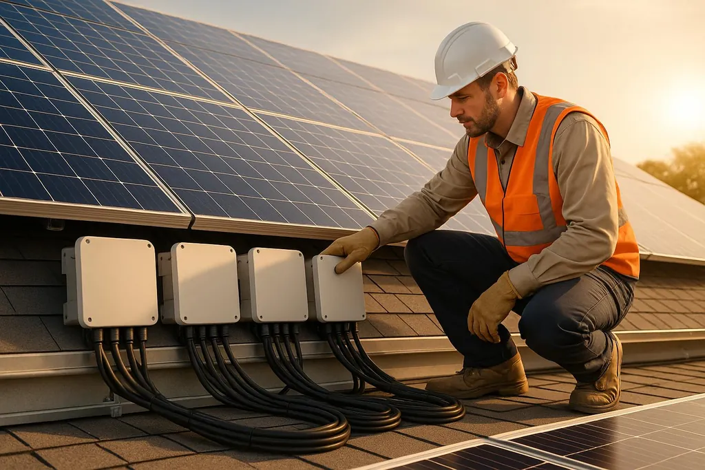
Learn essential practices for safely and efficiently wiring your solar system from DC to AC, ensuring optimal performance and compliance with codes.
Best Practices for DC to AC Solar Wiring
Proper wiring is essential for a safe and efficient solar system. Solar panels generate DC electricity, but homes use AC power. Here's what you need to know:
- Inverters: Convert DC power to AC for home use or grid connection.
- Wire Sizing: Use the right gauge to avoid voltage drops and overheating.
- Configurations: Choose series, parallel, or hybrid wiring based on voltage, current, and shading needs.
- Safety: Grounding, overcurrent protection, and labeling reduce risks.
- Compliance: Follow NEC Article 690 and local codes for installation.
- Tools: Wire strippers, MC4 crimpers, multimeters, and conduit benders simplify the process.
Planning for future system expansion is also critical. Proper wiring ensures efficiency, safety, and longevity for your solar setup.
How to wire off-grid and grid-tied solar inverters
Required Components and Tools for DC to AC Wiring
Having the right tools on hand is essential for wiring DC to AC systems safely and efficiently. These tools not only make the job easier but also help with accurate troubleshooting.
Wire Strippers and Cutters
Wire strippers and cutters are must-haves for preparing wires. They help remove insulation and cut wires to the right length. Look for tools that include built-in cutters, heavy-duty pliers for thicker wires, adjustable gauges for stripping, and ergonomic handles for comfort during use .
MC4 Crimping Tool
An MC4 crimping tool is designed to create secure, weather-resistant connections. It ensures both strong mechanical bonds and reliable electrical performance, which are crucial for long-term system stability .
Digital Multimeter
A digital multimeter is your go-to tool for measuring voltage, current, and resistance. For convenience, choose a model with auto-ranging capabilities that works with both AC and DC. Some advanced multimeters even offer features like temperature measurement and data logging for detailed diagnostics .
Solar Clamp Meter
A solar clamp meter is used to measure current in live circuits safely. Many models also measure voltage, resistance, and continuity, making them a versatile choice for troubleshooting and maintenance .
Conduit Bender
A conduit bender is essential for creating smooth, precise bends in EMT conduit. Properly bent conduit not only makes wire pulling easier but also helps protect the wiring from damage.
Solar Wiring Configuration Methods
Choosing the right wiring configuration is key to optimizing your solar system's performance, ensuring safety, and meeting your inverter's requirements.
Series, Parallel, and Hybrid Configurations
Series wiring links panels in a single path, increasing the system's voltage while keeping the current constant. For example, wiring four 12V panels in series results in a total output of 48V. This setup is ideal when higher voltage is needed to match your inverter's specifications, especially when all panels receive consistent sunlight.
The biggest benefit of series wiring is lower current, which allows for smaller gauge wires and minimizes voltage loss over long distances. However, there's a drawback: if one panel is shaded or fails, it impacts the entire string's performance, as the current must pass through all panels.
Parallel wiring, on the other hand, maintains the panels' voltage but increases the total current by creating multiple pathways. For instance, four 12V panels wired in parallel still output 12V but with four times the current.
This configuration shines in situations where shade tolerance is critical. Since each panel operates independently, a shaded or underperforming panel won't drag down the others. The downside? Higher current flow requires thicker wires and can lead to greater voltage drops, particularly over long distances.
Hybrid configurations combine the strengths of series and parallel wiring. For instance, you can wire panels in series to form strings and then connect those strings in parallel. This approach provides flexibility to meet inverter requirements while offering some degree of shade tolerance.
| Configuration | Voltage Effect | Total Current | Best Use Case | Shade Impact |
|---|---|---|---|---|
| Series | Increases | Remains constant | High voltage systems, uniform sunlight | High - affects entire string |
| Parallel | Remains constant | Increases | Shade tolerance, low voltage systems | Low - panels operate independently |
| Hybrid | Customizable | Customizable | Complex setups, mixed conditions | Medium - depends on design |
Once you’ve selected a configuration, make sure it aligns with your inverter’s specifications for optimal performance.
Matching Inverter Specifications
Your inverter’s specifications play a critical role in determining the optimal wiring configuration. Voltage, current, and MPPT (Maximum Power Point Tracking) requirements must all be considered.
Maximum Power Point Tracking (MPPT) inverters are designed to operate within specific voltage ranges, typically between 150V and 600V for residential systems. Staying within this range ensures the inverter runs efficiently.
Start by checking your inverter’s maximum input voltage rating. This is the highest voltage your solar array can safely produce without damaging the inverter. Keep in mind that solar panels generate higher voltages in colder temperatures, so it’s a good idea to add a 25% safety margin to your calculated maximum voltage to account for this.
Next, consider the inverter’s minimum startup voltage, which is the lowest voltage required for the inverter to begin operating. If your array voltage falls below this threshold - due to shading or other issues - the inverter won’t function. This value helps determine the minimum number of panels you need in series.
Current ratings are just as important as voltage. Inverters have maximum input current limits for each MPPT channel. Exceeding these limits can lead to damage or shutdowns. When using parallel or hybrid configurations, ensure the combined current from your panels doesn’t exceed these limits.
Pay attention to your inverter’s MPPT channel configuration. Many inverters include multiple MPPT inputs, allowing you to connect different panel orientations or types to separate channels. This feature is especially useful for rooftops with varying angles or shading, as it lets you optimize each section independently.
Finally, string sizing is crucial for grid-tied systems that require consistent power output. Most residential inverters operate best with string voltages between 300V and 500V. This typically involves connecting 8-12 standard residential panels in series, depending on the panels' voltage ratings and local temperature conditions.
Safety, Code Compliance, and Labeling
Ensuring proper wiring, adhering to safety standards, and meeting code requirements are essential for a well-functioning solar installation. These measures not only safeguard your system but also help avoid expensive repairs or adjustments down the line.
Safety Guidelines
Grounding is a key safety measure in solar installations. All metal parts - such as frames, rails, and enclosures - must be grounded to minimize the risk of electrical shock or fire. Ensure grounding conductors are sized according to code, and consider using a larger gauge if you anticipate expanding your system in the future.
Overcurrent protection is another critical component. When connecting multiple array strings in parallel, install DC-rated overcurrent devices on both the positive and negative conductors. Avoid using AC-rated breakers, as they are not designed for DC systems. Choose overcurrent devices that align with your system's specifications and house them in weather-resistant enclosures located near the solar array.
Modern safety standards also highlight the importance of rapid shutdown systems, which reduce DC voltage quickly in emergencies. Many newer string inverters include this feature, but older systems may require additional devices. If your installation is in a lightning-prone area, especially if it’s ground-mounted, consider adding surge protection to shield your system from storm-related damage.
NEC and Local Code Compliance

The National Electrical Code (NEC) Article 690 serves as the standard for solar installations across the U.S. It covers key aspects like conductor sizing, maintaining proper clearances, and clear labeling of system components. Since local requirements can differ - such as specific conductor sizes or additional clearance rules - review both the NEC and any local amendments before starting your project.
Some jurisdictions may have extra requirements, such as mandates for energy storage readiness or reinforced mounting systems for extreme weather conditions. It’s a good idea to consult your local building department early in the process to ensure your system complies with both national and local codes. Also, account for the time it may take to secure permits and schedule inspections, as these timelines can vary widely depending on your location.
Labeling and Documentation
Proper labeling and thorough documentation are vital for the long-term management of your solar system. Use durable, weatherproof labels for outdoor components to ensure they remain legible over time.
Keep a detailed site plan that maps out the locations of panels, conduits, and connections. Additionally, maintain records of equipment specifications, installation dates, and warranty details. These documents are invaluable for insurance claims, warranty services, or future upgrades. Store this information in a secure, weatherproof location near your main electrical components. Taking photos of the completed installation can also provide a helpful visual reference for troubleshooting or future modifications. Having this level of documentation ensures your system remains functional and easy to upgrade or repair when needed.
Installation Tips and Troubleshooting
Getting the wiring right for DC to AC solar systems is essential to avoid expensive fixes and to keep your system running smoothly.
Wire and Conduit Sizing
When it comes to wiring, the size of your wires and conduits can make or break your system’s efficiency and safety. Undersized wires can cause voltage drops, which not only reduce efficiency but also increase the risk of overheating. For most residential solar setups, 12 AWG wire works well for runs up to 100 feet with currents under 20 amps. However, always base your choice on the specific needs of your system.
To keep DC voltage drop under 3%, use this formula: _current × resistance per foot × round-trip distance_. If you find the voltage drop is too high, switch to a larger wire gauge to fix the issue.
Conduit sizing is just as important. According to the NEC, wires should occupy no more than 40% of the conduit space when you have three or more conductors. For instance, a 1-inch PVC conduit can safely hold about four 12 AWG THWN-2 wires. Always double-check NEC Chapter 9 tables for your particular setup. Overstuffing conduits can make pulling wires difficult and might damage the insulation, leading to long-term problems.
For longer runs, consider using a higher system voltage, like 48V, to reduce current and allow for smaller wires.
Cable Management and Weatherproofing
Good cable management isn’t just about keeping things neat - it also protects your system and makes maintenance easier. Use UV-rated cable ties or solar clips every 3–4 feet to secure wires, and leave 6-inch service loops at junctions to accommodate thermal expansion.
Weatherproofing is another critical step. When cables enter enclosures, use properly rated cable glands or strain reliefs. Angle the entry point downward to create a drip loop, which prevents water from seeping into the enclosure. For added protection, wrap electrical tape and self-amalgamating tape from the cable toward the connector, allowing water to shed away from the connection.
If your system is ground-mounted, protect cables by running them through buried conduit or using cable protectors where they cross walkways. Even minor damage to cable insulation can lead to performance issues over time, so don’t skip this step.
By managing cables effectively and weatherproofing carefully, you’ll reduce the chances of future problems.
Common Mistakes and Solutions
One of the most common wiring mistakes is DC polarity reversal. To avoid this, always use red cables for positive and black for negative connections. Double-check polarity with a multimeter before finalizing any connections. For added safety, consider marking the polarity directly on the cable jacket.
Another frequent issue is cable damage during installation. Inspect all cables for nicks or cuts, and test their continuity with a multimeter before powering up the system.
It’s also crucial to ensure that your system voltage matches the inverter’s specifications. A mismatch can lead to unnecessary losses.
As discussed earlier, properly securing and labeling connections can prevent many of these problems. When troubleshooting, start by checking for loose connections, verifying polarity, and measuring voltage under load. Often, what seems like a major system issue is just a loose wire or a simple wiring mistake that’s easy to fix.
Conclusion and Key Takeaways
Every detail matters when it comes to wiring a solar system - from selecting the right size and configuration to clearly labeling components. Proper DC to AC wiring not only ensures the system operates smoothly but also keeps it safe. Sticking to best practices and adhering to NEC and local codes significantly reduces electrical risks.
For readers of DIY Eco Homes, safe wiring does more than protect your home and investment - it also plays a role in seamlessly incorporating renewable energy into your daily life. Even small mistakes can lead to serious hazards, so accuracy and attention to detail are non-negotiable.
Refer back to these guidelines to solidify your understanding and help you build a solar system that's both efficient and dependable.
FAQs
What are the pros and cons of wiring solar panels in series, parallel, or a hybrid configuration?
When you wire [solar panels](/blog/how-to-choose-solar-panels-that-match-your-roof) in series, the system's voltage increases. This setup can help boost efficiency and reduce power loss when transmitting electricity over long distances. However, there's a downside: if one panel is shaded or not performing well, it can affect the performance of all the panels in the series.
On the other hand, parallel wiring allows each panel to work independently. This means shading on one panel won’t drag down the entire system. It's a more resilient option, but it comes with higher current output. That means you’ll need thicker cables, which can drive up installation costs.
A hybrid setup blends the strengths of series and parallel configurations. It enhances resilience while also offering backup power options. That said, these systems are more complex, and the added complexity often means higher installation and maintenance expenses.
What steps should I take to ensure my solar wiring meets NEC Article 690 and local building codes?
To make sure your solar wiring aligns with NEC Article 690 and local US building codes, stick to the NEC's guidelines for wiring methods, conductor sizing, overcurrent protection, and grounding. Always opt for PV-rated wiring that can handle outdoor conditions, secure all cables to prevent wear and tear, and install disconnects and overcurrent devices where required.
Don’t forget to review your local building codes, as they might include extra requirements beyond the NEC. For peace of mind and added safety, it’s a smart idea to consult a licensed electrician or solar installation expert. This not only ensures your system runs efficiently but also complies with all legal and safety standards in your area.
How can I plan my solar system wiring to allow for future expansion?
To get your solar system ready for potential future upgrades, it’s smart to start with an inverter that has a higher capacity than your current energy demands. This way, you won’t need a full replacement when adding more components later. Opting for scalable wiring systems and using microinverters can also make future expansions easier, as they minimize the need for extensive rewiring.
Be sure to stick to all applicable electrical codes, such as the 120% rule, to prevent overloading your system. It’s also a good idea to consult a licensed solar professional. They can assess your setup and confirm that your wiring and components are built to handle growth. A little planning now can save you time, money, and hassle later while keeping your system safe and running smoothly.